Andrew Wallace contributed to this article
In a previous article, “What is a smart AFE?,” I discussed smart analog front ends (AFEs) and how they represent the most recent advancement in closed-loop control. Many of the applications discussed in the previous article covered broader applications in the automotive and industrial markets. In this article, I’ll explore one industrial-focused application in more detail called thermoelectric cooling (TEC) control, including some examples how to use TEC, and how smart AFEs lend themselves to improving the implementation of TEC in systems that require it.
What is TEC?
TEC takes advantage of a phenomenon called the Peltier effect, named after Jean Charles Athanase Peltier, who discovered the effect in 1834 after finding that a current passing through two dissimilar conductors results in an increased thermal exchange, making one conductor hotter than the ambient temperature and one conductor colder than the ambient temperature. Typically, with a Peltier element, also known as a cell, current passing through forms a heat dissipation side (hot side) and a heat absorption side (cold side). This phenomenon has a very practical use, which is to heat or cool a material that interfaces with the Peltier element in a controlled way by controlling the current across the two conductors. Examples of applications requiring temperature monitoring and control include industrial laser markers, in-vitro diagnostics (IVD) equipment and automotive in-cabin temperature control.
Although the Peltier effect has been around for well over 100 years, it wasn’t until 1954 that H. Julian Goldsmid discovered and shared that exchanging semiconductors for the original conductive materials produced a much higher temperature gradient.
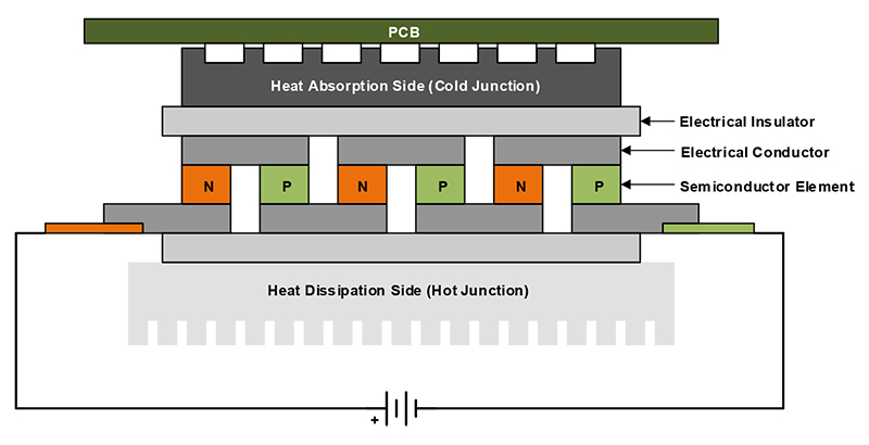
Figure 1 shows how the junctions form between electrical conductors and semiconductor elements, producing a temperature gradient for TEC with the use of a semiconductor-based approach.

Figure 1: Semiconductor-based Peltier element
Heat being released from a component or system that requires TEC moves from the heat absorption side of the TEC element and exchanges that heat with the heat dissipation side, which is cooled either passively through air cooling of a heat sink or actively through forced-air cooling or water cooling of a heat sink. Bismuth telluride is the semiconductor used most often in Peltier elements. In order to create large temperature differentials, these semiconductors need to have high electrical conductivity and low thermal conductivity.
Where and how can you use TEC?
Typically, one side of the TEC element acts as the hot side and one side acts as the cold side, but the interesting thing to note is that you can exchange the sides if you reverse the flow of the original current’s direction. Changing the polarity of the supply (as shown in Figure 1) reverses the direction of current in the Peltier element, causing the heat side to drop in temperature and eventually become the cold side, and causing the cold side or junction to become the hot side through progressive heating. This is useful when heating and cooling a sample rapidly in industrial medical applications.
Actively controlling the direction of current through the Peltier element increases the accuracy and speed at which it is possible to adjust a material to a set temperature by actively controlling the heating and cooling of that material. Many applications in IVD need this type of thermocycling, such as polymerase chain reaction. The medical devices responsible for these types of testing use TEC to heat a sample of genetic material to approximately 85°C and cool the sample back to approximately 30°C.
Smart AFEs and TEC control
Now that you know what kind of systems can use TEC, if we were to integrate these functions into a single integrated circuit it would need some kind of sensing input, memory or processing, and a control output. Most designers choose a discrete implementation, selecting an analog-to-digital converter (ADC) to sense analog inputs from the environment, a microcontroller (MCU) or memory for processing or addressing the ADC inputs, and then the MCU or memory to hand the corresponding digital information to a digital-to-analog controller (DAC) in order to output a specific voltage or current. The reason I mention this is that a smart AFE such as the AFE539A4 offers a holistic closed-loop solution for TEC, as it has these very components integrated within it. With these basic functions met, what else can the AFE539A4 do?
The AFE539A4 enables reconfigurability of its four outputs as either a DAC output or an ADC input for monitoring, which then gives you the flexibility to designate a channel’s function for a specific application or system. The integrated DACs offer voltage, current or pulse-width modulation outputs.
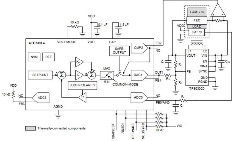
Figure 2 illustrates the versatility of the AFE539A4, which includes an integrated reference, nonvolatile memory, DACs or analog outputs, and ADCs or analog inputs for closed-loop control without an MCU. These integrated devices enable TEC current sensing and compensation, as shown on the right side of the figure, as well as direct negative temperature coefficient interfacing. The AFE uses this input data in a proportional-integral control loop to regulate the load to the temperature setpoint.

Figure 2: The AFE539A4 smart AFE configured for TEC control
In terms of interfacing and communicating with the smart AFE, users can choose between an I2C interface, Serial Peripheral Interface or a general-purpose input/output (GPIO) interface. The GPIO latching feature may also be useful for latching to a value when there is a fault condition, such as a high-temperature scenario where there may be a value designated for protecting the system during a fault or an environmental factor that causes overheating.
Conclusion
TEC is a well-known concept that previously required many discrete components to achieve the necessary closed-loop control. Smart AFEs offer input, processing and control in a single chip, specified across the full industrial temperature range of –40°C to 125°C in a 3-mm-by-3-mm package.
Additional resources


