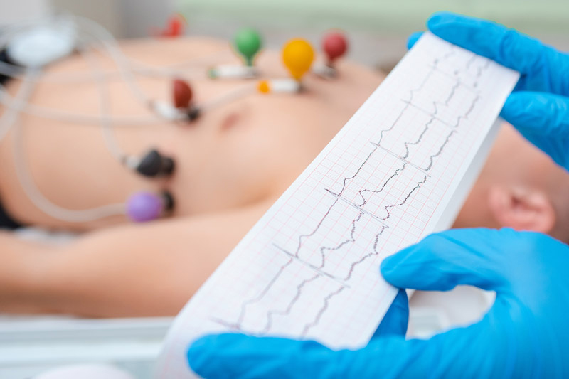
Other Parts Discussed in Post: AFE4950 With smartwatches and fitness bands widely used as personal health monitoring devices, the accurate acquisition of electrocardiogram (ECG) signals on these wearable devices has become a field of great interest. An ECG records activity in the heart through the acquisition of electrical signals. Conventional ECG systems such as patient monitors involve the connection of multiple electrodes to the patient. The signal acquired between a pair of electrodes is representative of the activity of the heart along the vector connecting the pair of electrodes, and gives a unique view of the heart. Figure 1 shows a multi-lead ECG signal acquisition system.

Figure 1: Multi-lead ECG signal acquisition
ECG signal acquisition on a wearable device like a smartwatch can be realized with electrodes that make contact to the left wrist and right hand. An electrode at the bottom of the wearable makes continuous contact with the left wrist, where the watch is worn. Then, to record the ECG signal, the user touches an electrode with their right-hand finger on the top or side of the device. While the right- and left-hand electrodes sense the ECG signal, a third electrode (for example, one in contact with the wrist) can drive the DC potential of the body and bias the electrodes to a voltage that is optimum to the ECG signal chain. Referred to as the right-leg electrode even though it is in contact with the wrist, it derives its name from its positioning on the right leg in clinical ECG systems.
There are some unique challenges and requirements for the electronics used for battery-powered ECG acquisition on wearable devices. Apart from the requirements of small size and low power, the analog front end (AFE) used for ECG signal acquisition also needs to overcome challenges of signal quality degradation resulting from small, dry electrodes. ECG signal acquisition using such electrodes suffers from high electrode-skin contact impedance, leading to potential signal loss and noise degradation.
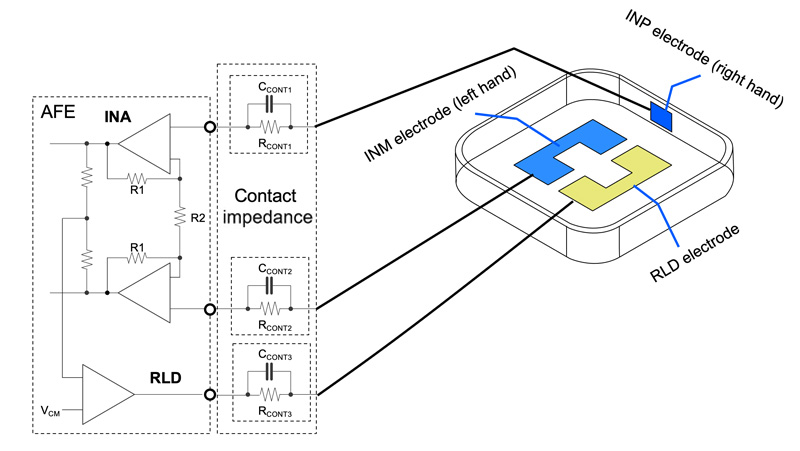
Figure 2 shows an overview of an AFE in which an instrumentation amplifier (INA) senses the ECG signal between the left- and right-hand electrodes, while a right-leg drive amplifier drives the potential of the body through the right-leg electrode. The section labeled as “contact impedance” represents a resistor-capacitor model of the contact impedance in series between each electrode and the AFE pins.

Figure 2: Overview of an AFE and its connection to ECG electrodes
Challenges from high contact impedance
Five of the challenges that can arise from high contact impedance include:
- Increased noise – High-contact impedance can be a source of thermal noise; it is essential to band-limit this noise in the signal chain in front of the analog-to-digital converter (ADC) in order to avoid aliasing.
- Signal attenuation – To prevent attenuation of the ECG signal, the input impedance of the AFE must be very high compared to the electrode contact impedance. With a biosensing AFE like the AFE4950, it is possible to connect the electrodes directly to the AFE inputs without shunt components that would lower the input impedance because the AFE requires no external filters involving capacitors in shunt. The right-leg drive provides a mechanism to set the appropriate common-mode potential without requiring shunt bias resistors. The high input impedance from the AFE keeps ECG signal attenuation to a minimum even when using small electrodes.
- Common-mode coupling – The mains (50 or 60 Hz, and its harmonics) is a source of common-mode pickup by the human body. Ideally, the differential nature of the ECG signal chain will reject this pickup. If the contact impedance between the right- and left-hand electrodes is high and mismatched, however, the common-mode pickup can get translated to a small differential signal that appears at the inputs of the AFE. Such a signal would then show up as a tone in the ECG signal at the AFE output. You can minimize the amplitude of this tone in two ways: by suppression of the common-mode pickup by the right-leg amplifier operating in closed loop, or by reduction in the common mode-to-differential conversion based on the high AC input impedance of the AFE at the mains frequency.
- DC offset – In addition to the contact impedance, the electrodes can also develop a DC offset voltage (modeled as a voltage source in series with each electrode). If the right- and left-hand electrodes have a different DC offset, it can manifest as a differential DC offset in the ECG input signal. Such a DC offset can be in the range of hundreds of millivolts, and can limit the useable INA gain. Operating at a high INA gain will increase the signal level at the ADC input and improve the signal-to-noise ratio of the ECG signal acquisition. The INA in the AFE4950 has a built-in high-pass filter that rejects the differential DC offset at the input and allows for high gain in the INA.
The AFE4950 biosensing AFE is well suited for ECG signal acquisition on wearable devices. To limit noise, its 300-Hz low-pass filter between the INA and the ADC acts as an anti-aliasing filter. For signal attenuation, its DC input impedance is in the range of 10 giga-ohms, keeping ECG signal attenuation to a minimum even when using small electrodes. The AFE4950 also enables synchronized acquisition of ECG and PPG signals; the time difference between appropriate points in these two waveforms has a high correlation to blood pressure, making the AFE4950 a good fit for implementing a cuffless blood-pressure monitoring feature on a wearable device.
The block diagram of the AFE4950 is shown in Figure 3.

Figure 3: Block diagram of the AFE4950
Challenge No. 5: R&D time
Finally, another common challenge in ECG wearables design is R&D time. An integrated solution like the AFE4950, paired with FDA-cleared HeartKey? ECG algorithms from B-Secur, can help designers make clinical-quality monitoring easier to implement by eliminating months of R&D. You can read more in the announcement of our companies’ solution, “B-Secur collaborates with Texas Instruments to provide powerful, medical-grade ECG/EKG monitoring for consumer wearable devices.”
Conclusion
Implementing health monitoring applications like ECG in wearable devices presents unique challenges. The AFE plays a vital role in surmounting some of these challenges and enables acquisition of clinical-quality ECG signals on a personal device like a smartwatch. Such a technology has immense potential in helping with health monitoring.
In the near future, we will witness a surge of smartwatches that sound an early alert to seek medical intervention for an impeding heart condition. These technologies will make it possible to measure vital parameters from the comfort of your home and share them with your doctor at the touch of a button. With our extensive biosensing portfolio that spans multiple applications like photoplethysmogram (PPG), ECG and bioimpedance measurements, we are helping unlock the full potential of health and fitness monitoring in wearable devices.


