This article appeared in Planet Analog and has been published here with permission.
Galvanic isolation is common in industrial and automotive systems as a means of protecting against high voltages or to counteract ground potential differences. Designers traditionally used optocouplers for isolation, but in the last few years, digital isolators that use capacitive and magnetic isolation have become more popular. With any such isolators, understanding the importance of their safety-limiting values and how to utilize them is important to system design.
In systems using isolators it may be important to ensure that their insulation remains intact even under fault conditions. To achieve this goal, component standards governing optocouplers (such as IEC 60747-5-5) or capacitive and magnetic isolators (such as VDE 0884-11) specify safety-limiting values. These values specify the isolator’s operating condition boundaries within which the insulation is preserved, even if the functionality is not.
Isolator failure modes determine safety-limiting values
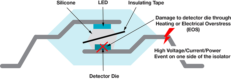
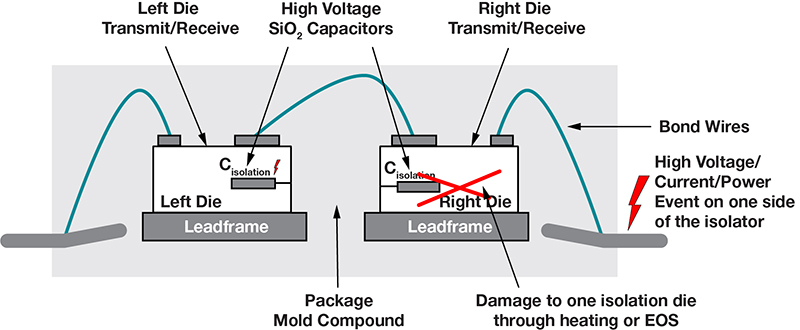
To understand what safety-limiting values specify, consider how isolators are designed. Figure 1 and Figure 2 illustrate the construction of an optocoupler and a capacitive digital isolator, respectively. In the case of the optocoupler, silicone material and insulating tape provide insulation between the two signal sides, while an LED and a photodetector provide the signal transfer. In the digital isolator, the series connection of two high-voltage capacitors on two separate silicon die provides insulation while electrical transmit and receive circuits coupled to the high-voltage capacitors provide the signal transfer.

Figure 1: A cross section shows how an optocoupler is constructed and the possible effect of fault conditions.

Figure 2: The digital isolator cross section shows how fault conditions can affect its insulating properties.
A high-voltage/high-current/high-power fault event on one side of the isolator can damage the circuits on that side. For example, events like short circuits, electrostatic discharge (ESD), and power transistor breakdown can force unintended high voltage and current into the isolator’s pins, damaging LEDs, photodetectors, transmit and receive circuits, and on-chip ESD protection. If there is enough power dissipated in the chip, there could also be significant structural damage to the circuits, such as fused silicone insulation, shorted high-voltage capacitor plates, or melted bond wires. Such structural damage can reduce the isolator’s insulation capability. The TI white paper, “Understanding failure modes in isolators,” discusses the effects of these fault events in more detail.
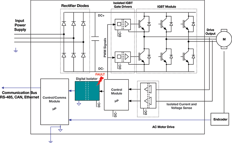
From the end-system perspective, isolation requirements may need to remain in force even after electrical and thermal stress events have impeded the isolator’s signal-transference operation. This is because damage to the isolation barrier can lead to secondary system failures, or the risk of an electrical hazard. For example, in Figure 3, a digital isolator protects the earthed control and communications module while the rest of the system floats. The effects of any faults in and around the digital isolator that may reduce the isolator’s insulation capability must be considered to avoid the effects of shorting DC- to earth.

Figure 3: Failure of the digital isolator providing protective isolation in an AC motor drive could compromise the entire system if the fault resulted in a short to earth.
The practice of safety limiting is designed to minimize potential damage to the isolation barrier should the isolator’s input or output circuitry fail. Isolator component standards define the safety-limiting values as the maximum input or output current (IS), the maximum input or output power (PS), and the maximum junction temperature (TS) the device can withstand in the event of a fault without compromising its isolation, even if the function of the coupling elements may be destroyed. Device manufacturers must specify these parameters, but it remains up to you to ensure that these values are not exceeded in the event of a fault or a failure so that there is no insulation breakdown.
As an example of manufacturer-supplied safety limits, Figure 4 shows the IS for different supply voltages and PS as a function of ambient temperature for TI’s ISO7741 digital isolator. These values are specified so that the device’s maximum safety junction temperature (TS = 150°C) is not exceeded. Based on these curves, for instance, at an ambient temperature of 100°C up to 600 mW of power may dissipate inside the device without any potential damage to the insulation.

Figure 4: The safety-limiting values for TI’s ISO7741 digital isolator show how much power dissipation a fault can impose without compromising the device’s isolation characteristics.
Circuits utilize safety-limiting parameters
The materials and circuit design parameters the manufacturer has adopted govern a device’s safety-limiting values. What the safety standards require is that optocoupler/digital isolator users provide adequate safety arrangements in their circuit design and ensure that the device’s application conditions not exceed the device’s safety-limiting values. Such safety arrangements might include current and voltage limiting that kicks in under fault conditions, or thermal management that prevents an operating temperature above a maximum value.
Let’s look at two example circuits for implementing safety limiting for a digital isolator. While these examples will not be exhaustive, identifying all possible faults and outcomes, they elucidate the principles of safety limiting and should provide a sense of how to approach safety limiting in your isolated-system designs.
For the first example, Figure 5 shows a digital isolator serving as the interface between an analog-to-digital converter (ADC) or analog front end (AFE) and a microcontroller (MCU). I’ll analyze this system for any one primary fault, including any secondary faults this single fault produces. (Additional circuits may be necessary to protect against multiple primary faults.) This analysis will focus on the MCU side for safety limiting, although you can apply the same principles for the ADC/AFE side as well.
In this example, a 24-V industrial power supply (variable up to 36 V) powers the MCU side (VIN24V). A DC/DC converter bucks this down to 5 V (VDC5V), followed by a low-dropout regulator (LDO) that creates a 3.3-V supply (VDC3P3V) for the MCU and the digital isolator. Current-limiting resistor RSUP is included in the supply path, and resistors ROUT and RIN are included in the input/output (I/O) path.
Figure 5: The digital isolator serves as an interface in this example, providing isolation between an ADC or AFE and an MCU.
Let’s examine some faults and their implications on safety limiting.
- Primary fault #1: Internal short in the isolator from VCC1 to GND1. The short circuit offers a resistance, RFAULT, from VCC1 to GND1. Using the maximum power transfer theorem, the maximum power dissipation within the isolator occurs when RFAULT = RSUP. The maximum power dissipation is equal to (VDC3P3V)2/(4 × RSUP). For very low values of RFAULT, the current through RSUP and VCC1 equals 3.6 V/RSUP. RSUP must be designed to dissipate this power. The power dissipated in the isolator itself, however, is very low (because RFAULT ~ 0 ?). Example: If RSUP = RFAULT = 20 ?, the maximum power dissipation in the isolator is (3.6 V)2/(4 × 20 ?) = 0.162 W. According to its spec sheet, this is well within the ISO7741’s safety-limiting power. For cases where RFAULT ~ 0 ?, the 20 ? RSUP must be a 0.65-W resistor to account for the power it will need to dissipate. A higher value of RSUP is always beneficial, since it reduces power dissipation under fault conditions. However, you must also consider the voltage drop across RSUP in normal operation. An isolator with a wide supply range (such as the ISO7741, which supports operation down to 2.25 V) or a very low-power isolator like the ISO7041 (which consumes only 100 μA/channel at 1 Mbps) are options that can support a higher value of RSUP.
- Primary fault #2: Input-to-output short circuit in the 24-V to 5-V DC/DC converter. In this case, the 24-V system supply (variable to 36 V) appears on the LDO input. To prevent further propagation of the fault, you must design the LDO to handle 36 V at its input. The isolator would likely not be able to withstand this voltage.
- Primary fault #3: Input-to-output short circuit in the LDO. In this case, the 5-V input of the LDO occurs at its output. To prevent further propagation of the fault, the digital isolator must be able to handle 5 V on its supply (the ISO7741 meets this requirement). You must also consider any damage to the MCU (if the MCU cannot support 5 V on its supply). In the worst case, the MCU I/O pins are damaged and offer low impedance to supply or ground.
- Primary fault #4: Short to ground or supply on the MCU IN and OUT pins. In this case, the current into the isolator pins can be higher than in normal operation. Resistors ROUT and RIN can help keep this current within safety limits. For example, ROUT = RIN = 100 ? limits the current through the isolator’s I/O pins to 50 mA for 5-V conditions, which is well below the ISO7741’s safety-limiting current.
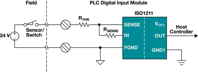
For the second example, an isolated digital input using the ISO1211 as shown in Figure 6.

Figure 6: In this example the isolated digital input circuit uses the TI ISO1211.
The isolated digital inputs receive signals from field sensors and interface them to a host programmable logic controller. The voltage input is nominally 24 V, but with variation can be as high as 36 V. The ISO1211 uses an external RSENSE resistor to provide a precise limit to the current drawn into the SENSE terminal. The external resistor RTHR can adjust the digital input’s voltage threshold. For an 11-V input threshold and a 2-mA current limit, the values of RSENSE and RTHR are 562 ? and 1 k?, respectively (see the ISO1211 data sheet for details).
- Primary fault #1: Internal short circuits inside the ISO1211 result in a low impedance of RFAULT between the SENSE and FGND pins. As before, the worst-case power dissipated inside the ISO1211 is (36V)2/(4 × RTHR). With RTHR = 1 k?, the worst-case power is 0.324 W, which is within the safety-limiting power for the ISO1211.
- Primary fault #2: A short circuit on external resistor RTHR. The built-in current limit on the ISO1211 limits the current draw from the pin to a value set by RSENSE. Resistor RTHR has no significant role to play in determining the input current, so shorting RTHR does not change the current going into the ISO1211 or the power dissipation very much.
- Primary fault #3: The input voltage rises to 60 V. Safety digital input systems must consider the 24-V industrial supply rising to 60 V under fault conditions. The ISO1211 can tolerate 60 V on its input pins while maintaining the current limit of 3.1 mA (RSENSE = 562 ?). The maximum power dissipated is 60 V × 3.1 mA = 186 mW, well within the safety-limiting power of the ISO1211.
These two examples demonstrate how to analyze and mitigate different faults in the context of safety-limiting values. Based on the actual application and safety goals, though, you may need to take additional measures.
Conclusion
When using isolators it is important to understand their safety-limiting values, and to make provisions in your design to meet these values. Failure to design for safety limits could result in faults generating extensive system damage and possible fire and electrical hazards should the isolator’s barriers fail. The example circuits demonstrate ways to ensure the maintenance of safety-limiting values under fault conditions.


