Have you ever designed a circuit that didn’t quite turn out the way you expected? I know I have! In this article I’ll help you resolve three common challenges associated with Hall-effect sensors in industrial and automotive applications – rotary encoding, robust signaling and in-plane magnetic sensing.
Challenge No. 1 – you can’t get a good quadrature signature for your rotary encoding application
When trying to monitor speed and direction (clockwise or counterclockwise) in a rotary encoding application, it’s common to use two Hall-effect latches, or a dual latch. Although there could be several reasons for a poor quadrature signature, one of the most common is the placement (and misalignment) between the device and the ring magnet poles.
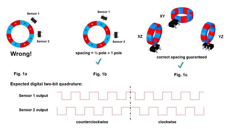
When using two Hall-effect latches, it is possible to mechanically achieve a decent two-bit quadrature output by spacing the Hall-effect sensors a half width apart from each magnet pole plus any integer number of widths. This is correctly shown in Figure 1b, where sensor 2 is located at the North/South interface, while sensor 1 is placed the width of one full pole plus a half width of the North pole away from sensor 2. For a dual Hall-effect latch, you could use a device that spaces its sensors exactly one-half the width of the magnet pole. Of course, this is very limiting because you have to match the spacing to the ring magnet poles.
Figure 1a illustrates the potential placement issues with using the two-sensor solution, while Figures 1b and 1c show how to fix it using two separate sensors or a single-chip solution, respectively. Hall-effect current sensors such as the TMAG5110 or TMAG5111 inherently help ensure a good signature for many ring magnet sizes and pole counts. Additionally, their simplicity in implementation eliminates any errors that could be introduced during mechanical placement. The precision also provides consistently accurate readings for a good quadrature signature.

Figure 1: Two-sensor rotary encoding: Fig. 1a incorrect sensor placement using two latches; Fig. 1b correct sensor placement using two latches; Fig. 1c multi-position sensor placement using a 2D sensor
Rotary encoding applications are prevalent in many automotive and industrial applications. Here are some examples:
- Automotive – power windows, sunroofs, lift gates, sliding doors and power seats.
- Industrial – garage door and gate openers, thermostat dials, home appliance knobs, wheel rotational sensing, and motorized window or door blinds.
Challenge No. 2 – your off-board sensor communication is not as robust as you’d like
If you’ve encountered this problem with your design, there’s a good chance you’ve used a sensor with a voltage output that has interference magnetically coupled into it. Although your trace may have been short, if there is a lot of electromagnetic interference (EMI) that you can’t account for, then your analog signaling may be coupling this interference directly into your measurement. Having a reliable link between the sensor and the microcontroller (MCU) enables the MCU to know whether the sensor is connected or disconnected. With a voltage output device, the output may be pulled to a low voltage or disconnected altogether – and the MCU will not be able to detect the difference.
EMI is extremely difficult to eliminate. Shielding, careful wire rerouting and other mitigation methods can add cost to your design. My suggested solution focuses on the sensor itself. Two-wire current-output devices are inherently less sensitive to electrical noise, making them a great option for remote sensing applications with medium-length cabling. Although sending the signal over a really long wire causes voltage losses, for most industrial and automotive applications, implementing a two-wire current-output sensor will work just fine.
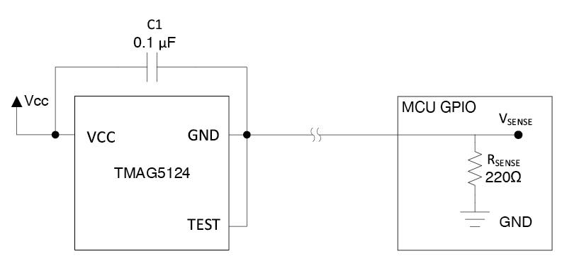
Figure 2 shows how a Hall-effect switch with a two-wire current output such as the TMAG5124 can transmit a signal over a longer distance using the ground connection. “Two-wire” in this case denotes having to connect the VCC and GND from the sensor to the general-purpose input/output of the MCU. Couple the current output feature with higher precision (2mT variation in magnetic field operating and release points), and you should have a solid design.

Figure 2: Implementation of a two-wire current output sensor
Automotive applications that use a current-output sensor include:
- Seat-belt buckles.
- Seat position/occupancy detection.
- Door latches.
- Parking brakes.
- Sunroof/trunk closures.
- Brake pedals.
Challenge No. 3 – your Hall-effect sensor is sensitive only to orthogonal magnetic fields
Most single-axis Hall-effect sensors available today detect magnetic fields that are perpendicular to the face of the package. Your choices are limited if you need a sensor that can monitor magnetic fields parallel to the side of the package.
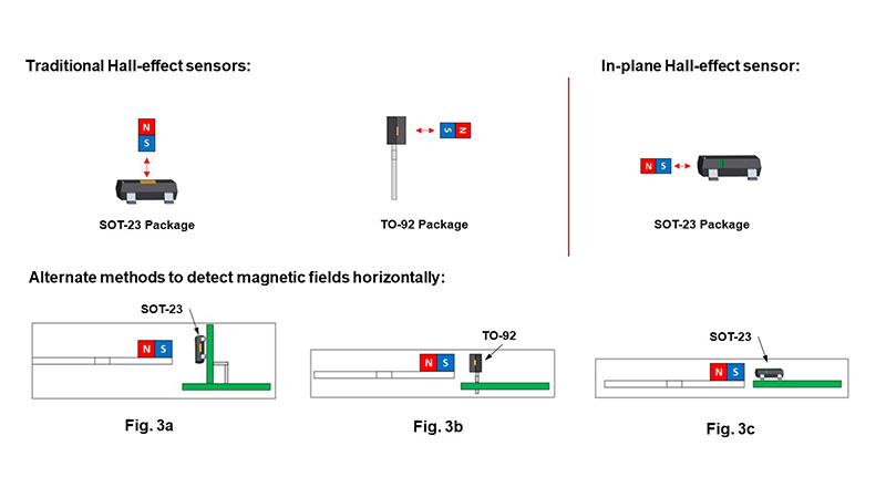
Figure 3 illustrates various ways to ensure horizontal magnetic field sensing. While it is possible to achieve horizontal magnetic field sensing with traditional Hall-effect sensors, there are some significant drawbacks. Mounting a standard 3-pin small outline transistor (SOT-23) package onto another smaller printed circuit board adds cost and complexity to the assembly process (Figure 3a). The transistor outlines (TO-92) package does not follow the same assembly mounting process as standard surface-mount packages, and will also add cost to the total design (Figure 3b).
If you encounter a similar situation, an in-plane Hall-effect switch like the TMAG5123-Q1 that can detect magnetic fields from the side of the surface-mount package is a good choice. It allows more freedom and flexibility in the mechanical design, because it leverages SOT-23 package and can potentially occupy a smaller space (Figure 3c).

Figure 3: Horizontal magnetic field sensing: Fig. 3a traditional sensor in SOT-23 package; Fig. 3b traditional sensor in TO-92 package; Fig. 3c in-plane sensor in SOT-23 package
Design challenges arise almost constantly, but there are usually methods or devices that can help you get around them. I hope that I’ve provided a few ways to fix some of the most common application challenges when designing with Hall-effect sensors. Comment below if you’d like to share some of your problems, and how you’ve fixed them!


