(Note: Bob Hanrahan co-wrote this article.)
Hardware engineers are often expected to deliver results while on tight project timelines. Circuit and system designers must use all of the tools at their disposal to create accurate, robust designs that work well the first time. Those demands, coupled with today’s dynamically changing work environments, mean that tools that you can use at home or remotely for circuit simulation and verification are more valuable than ever before.
Here at TI, we've seen that engineers are reducing the prototyping and evaluation phase of designs; in some cases, they are moving straight to a final printed circuit board (PCB) – yet everyone wants to reduce the risk of circuit errors. To that end, we identified a growing need for a high-performance, full-featured analog simulation platform. So together with Cadence, TI has launched PSpice? for TI, a full-featured version of the industry-standard OrCAD PSpice environment, which makes it easier to simulate entire subsystems for component evaluation and verification.

Ready to start simulating?

First, why use SPICE simulation?
Simulation program with integrated circuit emphasis (SPICE) has been helping engineers solve hardware design problems for decades. Circuit simulation has three primary use cases:
- Device evaluation. It is possible to measure the performance of specific products in specific applications, sometimes even before real devices or application circuits are physically available.
- Design verification. Building and simulating complex board- and system-level designs before building physical prototypes gives engineers confidence in their circuits and reduces design time. Design verification includes the ability to simulate circuit operation in worst-case conditions, ensuring proper operation if parameters such as temperatures, voltage extremes and device tolerances shift after product release.
- Design debugging. When things don’t go as planned, engineers often turn to simulation to troubleshoot problems or vulnerabilities in their system. Instead of reworking and testing real PCBs, a SPICE simulation can find and initially test circuit fixes.
Leveraging the power of circuit simulation for any or all of these tasks using PSpice for TI helps you reduce development times and get to market faster. There are also inherent benefits to simulation given its computer-based nature. For example, now that working from home is more common, using simulation means that you can make significant progress from anywhere on your projects. There’s also no waiting for parts, PCBs or lab equipment – just build your simulation test bench and go.
You can electronically share circuit simulations easily with other team members for larger system-level simulations or peer-design reviews. You can also run more complex tests such as parametric or temperature sweeps, sensitivity analyses, or device tolerance analyses in ways that would be costly and time-consuming to perform in the real world.
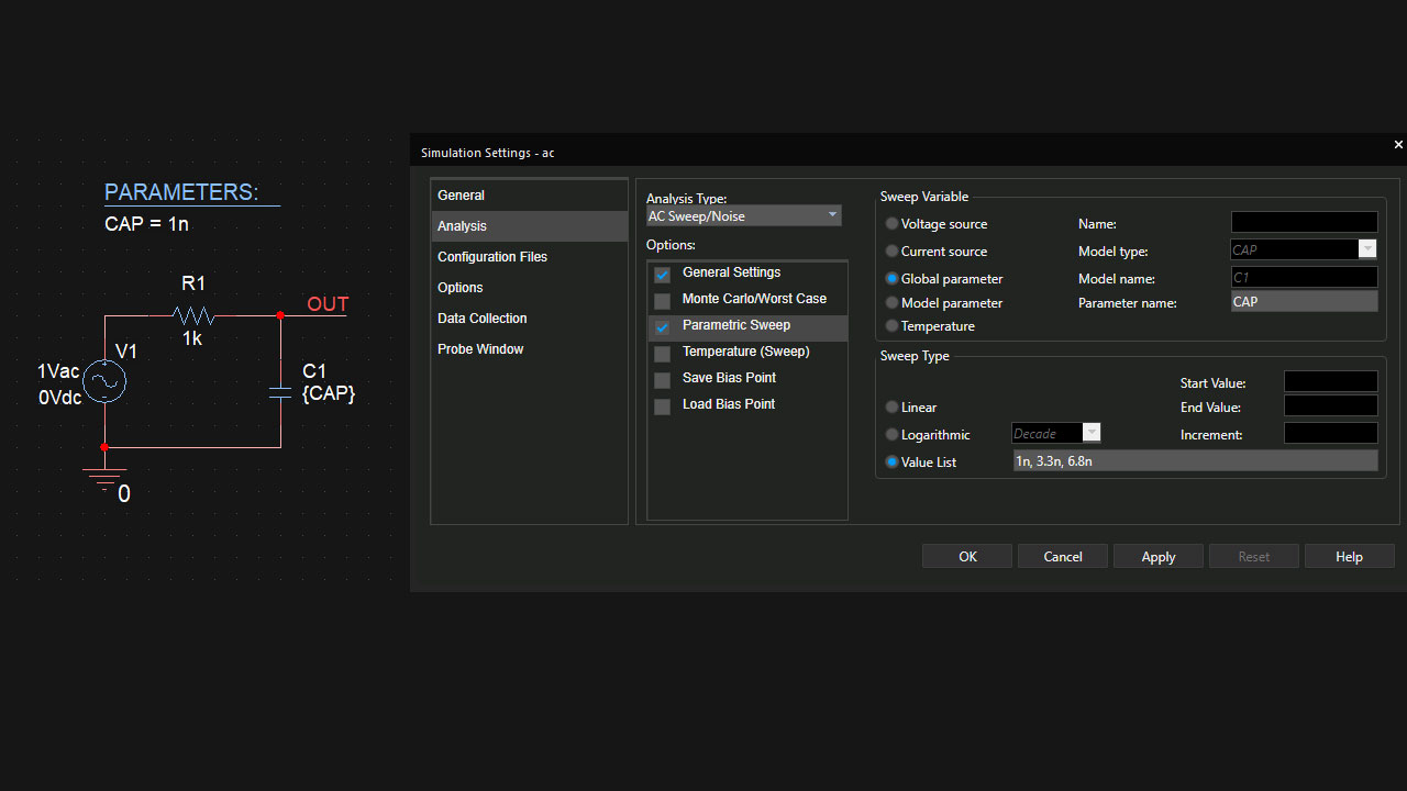
Let's look at an example of this in PSpice for TI. The simulation set up in Figure 1 plots the AC transfer function of a single-pole resistor-capacitor filter network while stepping the value of the capacitor.

Figure 1: PSpice for TI schematic and simulation profile example
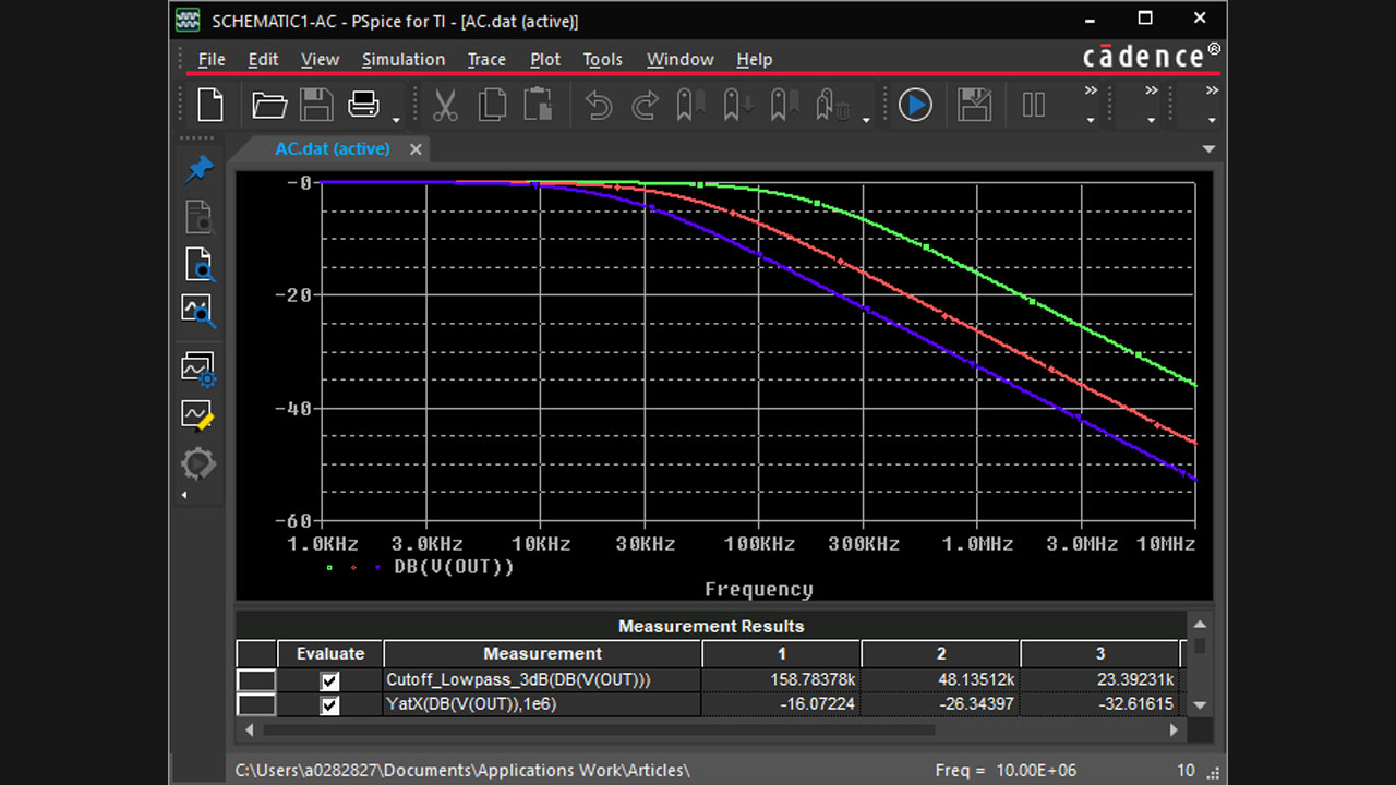
Figure 2 shows the resulting plots, along with automatic measurements of each plot’s -3-dB bandwidth and gain at f = 1 MHz. This powerful analysis capability can greatly expedite design optimization.

Figure 2: PSpice for TI simulation and measurement results
An important note is that proper simulation results assume the device models are accurate and they converge (which in this context means to arrive at an answer) quickly. Thankfully, TI has some of the most accurate and convergence-friendly models in the semiconductor industry, and is continuously working to develop new models and improve its overall modeling capabilities.
Why use PSpice for TI?
PSpice for TI provides both schematic capture as well as analog circuit simulation. Far from being a limited trial, it harnesses many of the advanced features found in the commercial version of the tool, including automatic measurements and post-processing, as well as Monte Carlo and worst-case analysis. PSpice for TI is built on the latest PSpice release, works when offline, is compatible with projects developed in the commercial version, and offers an unlimited number of nodes and measurements when using TI devices.
Speaking of TI devices, along with a standard suite of component models, the complete library of nearly 6,000 TI analog power and signal-chain models is fully integrated into PSpice for TI, enabling you to add TI parts to your projects with just a few clicks. There’s no need to manually import TI models, and the rapidly growing library will automatically update to stay current with what’s available on TI.com.
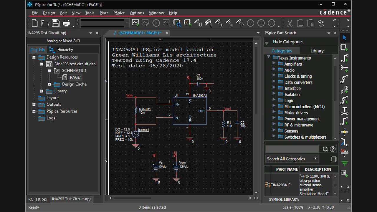
Most TI device models come with a fully tested and operational design example, and in many cases, a complete reference design from which you can cut and paste. This is a great way to quickly get started with a design and rapidly see device operation and performance. You can place a component and open a related reference design with just a few clicks in the tool. Figure 3 shows an example of just one such design example that is ready for modification and simulation. The figure also shows the application’s new dark mode and customizable color scheme, which reduces energy use and may help reduce eye strain.

Figure 3: TI device reference design example
To further help you make quicker design decisions, the tool provides easy access to TI product details and data sheets, and relevant queries for support from the TI E2E? support forums. A library of tutorial videos is also available within the environment.
To add SPICE simulation to your engineering workflow, download PSpice for TI and start reducing your design time, along with the community of engineers already making use of this powerful tool.
Additional resources
- Find reference designs leveraging the best in TI technology to solve your system-level challenges.
- Start a new power-supply design with in-depth calculations of voltages and currents using the Power Stage Designer? software tool.
- Explore the TI Precision Labs video training curriculum for analog signal-chain design, from foundational knowledge to advanced concepts.
- Download WEBENCH? Power Designer, a popular, free online power design tool that takes basic input and output specifications and quickly provides a full schematic and bill of materials (BOM).
- Explore TINA-TI?, a flexible SPICE-based simulation platform that supports a broad range of components, yet maintains a basic user interface sufficient for many analog designs.


