Stepper motors come in many different varieties, but there are two main winding configurations for permanent magnet and hybrid stepper motors driven by two phases: unipolar and bipolar. The common wiring configuration for unipolar motors is six wires connected to the motor windings (A+, A-, B+ and B-) and a center tap on each phase connected to the motor voltage supply, Vm, as shown in Figure 1.
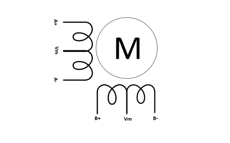
Figure 1: Six-wire unipolar stepper motor winding connections
In this configuration, the motor commutates by switching each section of the motor windings on, meaning that current only needs to flow in one direction. This configuration makes drive circuitry somewhat simple to design, as you need only four low-side switches plus recirculating diodes to turn on each section of the windings. Figure 2 illustrates this configuration with the DRV8805, a 2.0-A unipolar stepper motor driver.
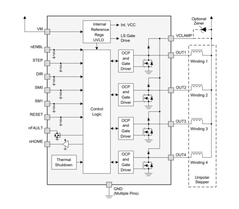
Figure 2: The DRV8805 wiring when connected to a unipolar motor
The trade-off for design simplicity is that at any given moment, the motor is only using half of the windings, preventing full torque capability.
In contrast, bipolar stepper motors only have four wires connected to the motor windings, which are also labeled A+, A-, B+ and B-. As shown in Figure 3, bipolar stepper motors have no center Vm tap.
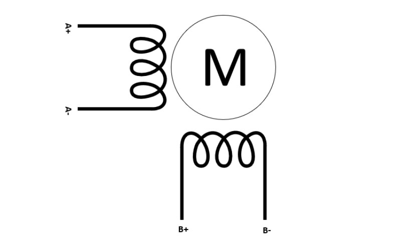
Figure 3: Four-wire bipolar stepper motor winding connections
Because of the lack of center taps, bipolar stepper motors need current to flow in both directions in the windings, and thus need more electronics to push and pull the current. It is now possible to turn on the full winding, resulting in higher available torque as opposed to the unipolar winding configuration.
With some minor reconfiguration of the winding connections, you can operate a unipolar stepper motor as a bipolar stepper motor. To do so with a six-wire unipolar motor, leave the center Vm taps in each phase disconnected and taped off with electric tape. As Figure 4 illustrates, this wiring configuration, also called bipolar series, now allows bidirectional (bipolar) current flow in the motor windings.
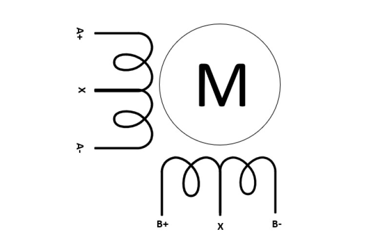
Figure 4: Configuring unipolar stepper motor windings for driving as a bipolar series stepper motor
Some fundamental trade-offs do exist with this reconfiguration. A bipolar series configuration energizes the full winding, thus achieving higher torque at holding positions and at lower speeds compared to a unipolar stepper motor. This gives the bipolar series stepper motor higher overall inductance, however, and at higher speeds causes the effective torque to drop at a faster rate than that of a unipolar configuration (Figure 5).
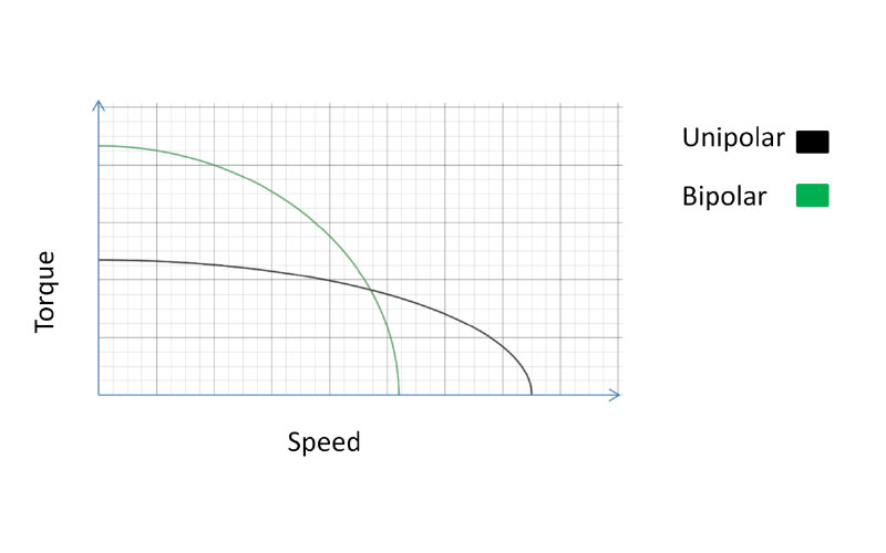
Figure 5: A unipolar vs. bipolar series stepper motor torque/speed curve
This behavior is due to the inverse proportional relationship of output torque vs. speed and inductance, as expressed in Equation 1:
 (1)
(1)
where τ is the torque, Vm is the motor supply voltage, v is the motor speed and L is the motor inductance.
Many applications can use unipolar or bipolar stepper motors in their systems, including heating, ventilation and air-conditioning electronic expansion valves, ATM modules and printers. Using a bipolar stepper motor driver integrated circuit, regardless of stepper motor type, has advantages. You can:
- Reduce the time for board redesign between systems with different motor types,
- Source fewer components, and
- Offer a broader range of products and performance.
Stepper motor drivers like TI’s 20-V, 2.0-A DRV8847 and 50-V, 1.5-A DRV8436 provide the flexibility to drive both unipolar stepper motors and bipolar stepper motors. We also offer dedicated unipolar stepper drivers like the 2.0-A DRV8803, DRV8804, DRV8805, and DRV8806.


